Phred
Free Member
-
Joined
-
Last visited
Everything posted by Phred
-
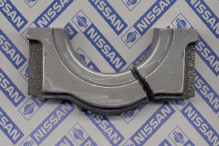
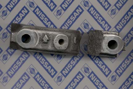
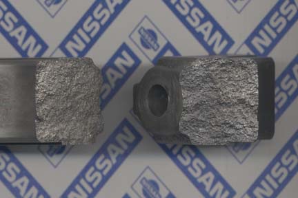
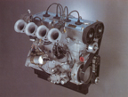
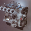 A safe rev limit is like safe sex, there's still plenty of risk involved. Its also a very open ended question. I'll try to explain the variables that effect and change rev limits. First, the part everyone is aware of, displacement/stroke. An L-24 has less mass and stroke than an L-28, so its physically easier to throw a smaller pist/rod/stroke back and forth. So generally it can handle higher revs before it flies apart. You can quickly see why lightweight components are important for high revs. Less weight means less stress on everything that goes around or up and down. Balance, the higher the revs the more important balance is. If you have a balanced crank, and an unbalanced rod/pist. assembly, it can literally rip the crank out of the main caps at high revs. (see pics for proof). Note: to help prevent this, main caps are reradiused, and shotpeened. Then attatched with an ARP stud kit. Balance moocho important. Ok, so its perfectly balanced. Everything needs oil to continue going around. All a deep sump does is ensure a larger supply to draw from. Volume, for continually suppling fresh lube to the bearings. Pressure, ( rule of thumb here) ten pounds for every thousand revs used when hot. Z cranks have another limiter. The supply of oil to the rod bearings. The Z crank delivers oil to the rod bearings through the main bearings. But its not an equal system. the center main feeds two rods, while the rear main dosen't feed any. It works ok to 7000rpm, but if you want extended high rpm, the crank must be cross drilled, and heat treated ( another subject). Yes, I know drag racers can turn 8000+ on a stock crank. But an entire season lasts about as long as one SCCA practice session. I know the difference, I have built L-cranks that can last a full season in a GT-2 9000rpm engine. Point being, high revs? how long? how often? and how long do you expect your engine to last? I could go on, but I think you're getting the idea. Other considerations, everything else in the engine that will allow it to turn higher revs effectively. In the mid eighty's I had a customer with two L-28 GT-2 engines. One had steel valves, retainers, and a cam which gave max power at 8200/8500rpm, depending on cam timing. The lowest rpm it would run at was about 4000rpm. It wouldn't rev any higher because there was too much weight in the valve train, and it would float the valves. So the other engine had Titainium valves and retainers, and a cam that was designed for higher revs. This one would rev reliably past 9000rpm with less valve spring pressure, and of coarse it made more HP, alittle over 300. But it also didn't want to run under 4500rpm. While on this subject, I have to say that Titainium retainers are a waste of money unless the engine will see very high revs. There's much more to consider than high revs. Budget, intended use, expected life, and the ability to transform all those high revs into usefull energy. Remember to look at the engine as a whole puzzle, not just one component. Phred
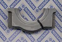
-
Loren, I ran alu. pin buttons on the old Spridget race engins. The only problem I had was on the first set which didn't have enough purchase in the pin bore. I also had them fit in the pin bore with a few thou clearance thinking they would expand. This was not the case and they started to loosen in the pin and I caught it just before disaster struck. The sucsessfull alu. buttons had a .001 press fit, and were hollow ( except for the area that contacted the cyl. wall.) The press fit didn't effect the pin O.D. as the crush collapsed the hollow button. Then I fit the length to have end clr. of .005. I machined the end of the button the same radius as the bore dia. I tried a smaller radius for less friction area on the bore, but these quickly wore and then had too much end clr. If you have a nice honed pin I.D., a slip fit will work with at least .625 purchase. The Lycoming Aircraft engines use buttons with a slip fit and one inch of purchase in the pin. I patterned mine after these. If you use a slip fit type, be sure to drill a couple of small holes in the fillit between the small and large dia. of the button. this will allow oil to drain out of the pin/button. If you don't do this oil will fill up in the pin, and screw up the balance. Thats one of the reasons I used a pressed/sealed fit. The picture is a Lycoming button I had from my old aircraft days. Phred

-
Hi Loren, My last contact with them was 11-18-02 Nissan North America-Motorsports 745 West Artesia Blvd. Compton, Ca. 90220 Phone: 310-538-1462 Fax: 310-538-1462 PS Spence got the pole at Eureka last week end.
-
I've been an engine machinist for over twenty five years. I have seen more blocks screwed up by people trying to save a buck, and doing it at home. If you try to do this in the car, with the crank and and pan still installed. Save your time. Instead, just grab gun and shoot yourself in the foot. I've always tried to be diplomatic in my posts, but this kind of home machining is just plain stupid. Take the block to an auto machine shop and request a "ring finish" hone job. Only a few tenths of a thousanth of an inch will be removed. And it will be done with a ridgid two stone, two shoe hone. Most probably a Sunnen hone. And it will be done while flooding the hone with specific honing oil, designed to carry away the grit from the wall and stones. It also keeps the stones cutting, and not clogging up. This will tend to straighten the bore and put the proper cross hatch pattern on the cyl. wall. I can't tell you how many times people have come to me wondering why their rings didn't seat after they ball honed their cylinders at home, and then put new rings in. Were you aware that there are even different grit stones used, depending on the type of rings used? Cast iron, moly faced, chrome, steel, each type ring has a specific grit finish that allows the ring to properly seat. Even the intended use of the engine can be a determining factor in the type of cylinder finish used. Do yourself a favor. Unless you really know what your doing. Have it done professionally. Your engine will thank you. Phred
-
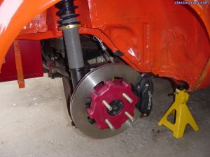 Do I see a spacer between the caliper halfs? And which caliper? Superlite cast? Dia. of rotor? Looks good enuf to eat. Phred
 -
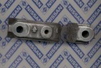
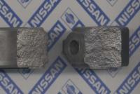
FWIW I don't have a clue what these cast in numbers indicate. Found on the first counterweight, cast into the crank, I found these #'s on an L-28 P3040. This crank was out of an 80'ZX. I also have an LD28 crank, unknown year, and it is cast with a VO740. Phred
-
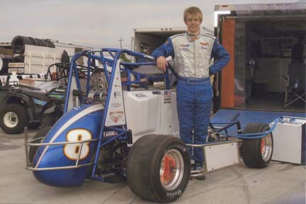
Sopwith21, I raced in SCCA for eighteen years in H-Prod, Spec Racer, Gt-3, Gt-4, and a few enduros in Sports racers. I am now a crew chief on a USAC Midget. These cars are animals. All up race weight is 950 lbs, with 350 horsepower. The power to weight ratio is much better than a formula atlantic car. And the're only designed and tuned to turn left. I wish I would have known in my road racing days, what I have learned in Midgets. That is, how to tune stagger and shocks for handling. Just for reference, a midget runs about three and a half inches of stagger in the rear. If we have trouble hooking up the rear on exit, we'll soften the RR spring, and or, sway bar, and or, decrease front rebound resistance to transfer weight to the rear. Also you can adjust stagger with pressure changes without effecting the tires ability to grip, as long as you stay within the tires working temp. range. Sure, you might not have perfect temps across the width of the tire, but sometimes stagger is more important. We test much more now than when we were roadracing, because there are more areas to tune to make a car turn left, than there were to make a car turn both ways. I'm still a roadracer at heart, but this type of racing is very exciting, and very challanging to tune the car. Summary: don't be afraid to try new things, keep good notes, and always try to make the car better, even if other people think you're a staggering drunk. Phred

-
SuperDave, I'm afraid you have a problem child there. First, a crank can be straightened. But I think you're over the limit. I have straightened many cranks, but never one that was off that much. Its very common to remove .002/.003 of runout by straightening. I probably would not even attempt .004. Think of this, you hopefully have about .0025 main brg. clearence. So if you have a crank that ossilates its center journal up and down .006 every revolution, in very short order you will wipe out that journal/bearing, along with # 1 & 7 bearings. Crankshaft runout is the first thing that should be checked before a crank is balanced. If you balance a crank, then straighten, the balance will be off. The center mass of the crank is now in a different spot and will be reflected by an imbalanced crank. Crank Straightening 101- A crank is straightened by placing it in protected v-blocks, and then, using a custom ground large chisel, is smacked fairly hard with a large ball peen hamer (on the LOW side of the runnout !), in the fillet (radiused edge) of the journal. Sounds horrid huh? The chisel is formed to the same radius and diameter of the fillet, and if done correctly, will not damage the journal/radius. Hitting the fillet in this way causes an interesting metalergical/granular reaction, and the crank will draw itself upward, and will straighten itself without the terrible stresses imposed by pressing on the high side ( a real big no-no in crankdom). There's a bit more finesse' to it, as you can have runnout, and straighten, in areas other than the center main. But thats basically the method. So what do you do? (A) If the crank hasn't been balanced, and you haven't spent anything on it, get another one. ( This crank won't even clean up by grinding it .010, but if you just have to use this crank, I would straighten it as best as I could, (at least .003), and then have it ground .010, and then balanced. I know this isn't what you wanted to hear, but live and learn. Crank condition, both journal condition, straightness, and balance, is one of the first things to consider when building up a race engine. Phred
-
I have used a number of different makes of adjustable cam gears. Most work great. I have also built a few, and have one in the works right now. It takes a lot of machining, and would be too expensive to build one at a time to sell. But for my own use, my time is cheap. Unlike the stock gear which has three holes, seperated in four degree increments. Or the optional gear which has eight holes seperated in three degree increments, an adjustable gear can be set anywhere you want. When using an adjustable gear, you should use at least a 12 inch diameter degree wheel to do your timing. After all, your splitting hairs, so you need to be as accurate as you can. You also need to know a lot about your engine, cam, and how it will be used, for it to be worthwhile. Phred
-
Great summary on the little tin can. Stick around, this is a great site to learn and teach other Z wierd'os. Phred (sort of old motor head)
-
Its very unsettling to think you have no control over when one of these things might sputter and quit. I have seen new condensors start to stutter and miss, right in front of me on the dyno. Put another one on and it might last five years, or five minutes. I have a theory. I think that inside those little metal containers are some very tiny women. Sometimes they work fine without any attention at all. Then, for no reason, they'll spit at you and quit. Can't trust em'. Condensors I mean. Phred
-
Hi Ed, Torque nuts to 60 ft. lbs. with moly lube on the threads and under the nut. remember to install the studs hand tight only. Phred
-
ZSaint should know this as he has smacked more than one piston into a head. What it gets down to is known as Piston to Head Clearance. Basically, you just do whatever is required to keep those two important parts from hitting each other. The magic number varies a bit depending on the type of engine, rods, and RPM. For Z engines, (that will not go past 7000) the magic number is about .037. I have snuck up on that number a little at a time. At .037, the piston will just be so close as to not even let carbon build up, but not cause damage. I did one at .032, and it left a mark on the head. So to be safe consider .042 a minimum. Nissan gaskets will compress to about .045. which is to say, if you have a plus .003 deck height, you're ok. Depending on what head you have, the edge of the piston can whack the head in different areas. When pre-assembling, I always put a little childrens modeling clay in the suspect area, bolt the head down, and run it through one revolution. Then carefully remove the head and cut sections of the clay out with a razor blade. You will be able to see excactly where the danger points are. Then I'll either touch up the close areas with a die grinder, or if I need more, take the pistons to the mill, and take a bit off the domes in a more accurate manor. Phred
-
Try: www.wolfcreekracing.com Phred
-
This is an area that can have more than one right answer. So you will always be able to find various specs. First I'll be general, then specific. The ring needs clearance between its ends (end gap) when installed in the bore. This is to allow for expansion of the ring when it gets hot. There are various sizes and designs of rings, and they will expand more, or less, depending on there mass, material, and location. Even the type of induction, and jetting, will affect ring gaps. So when you see a recomended gap of .017 for an L28, you know it will be safe for all models of that engine. This is based on a very simple formula of .005 (gap) per inch of bore. SteveK said he measured .020 in his L28. This would indicate a bore .001 larger than stock. This has to do with the formula for circumference/bore and Pi (3.1416). Just know that for every .001 inch of bore dia. changed, the end gap of the ring will change .003. So in answer to his question, yes those gaps will work fine, even though they are a bit on the wide side. Just for reference, I found that end gaps can be reduced to .014 on certain race engines without butting the rings. The reason you hear such a fuss about ring gaps is because they can be a race engine builders friend or enemy. Too wide, it runs ok, but a slight amount of compression is lost. Tighten them up, more compression and horsepower. too tight, the ring gap is lost, the ring is forced into the cyl, and damage occures. Enter gapless rings. TotalSeal provides sets which include a conventional top ring, and a modified two piece second ring which uses a "rail" (like on on oil ring) to stop compression gas from leaking past. I have used these rings on many engines, and have not had any problems with them. Phred
-
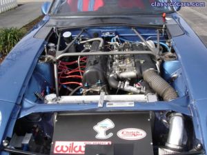 Eric, good job. Tell me about the cowl, I don't see any vents. You have done many of the mods, I have in mind for my Z. Phred
 -
Hi Loren, Cast pistons will do fine with .0005. Forged pistons like .0008. the rods also need .0008, if they're bushed or not. You can guesstimate the .0005 by having a pefectly clean pin bore and pin, with some WD40 on the pin and bore the pin will just slip through by its own weight when you hold it upright. The old Mercedes needed .0012/.0015 cause the driver was always over reving it. Phred
-
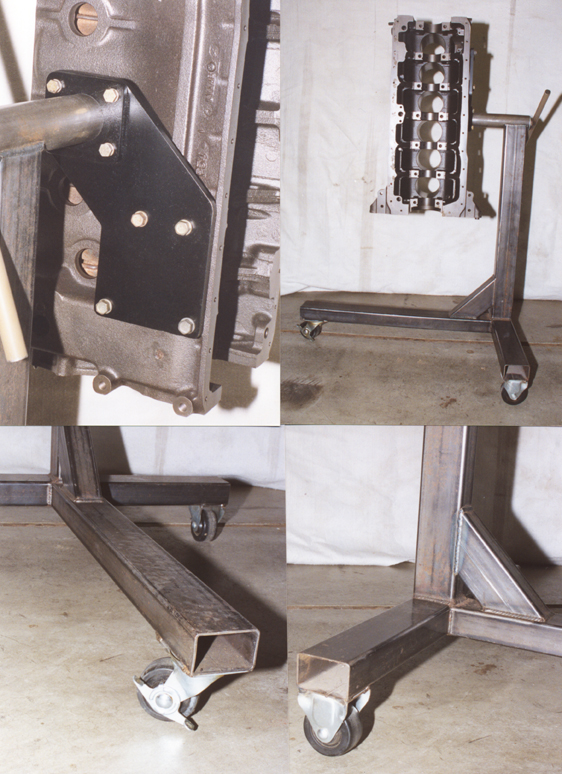
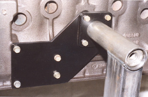
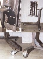
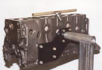
I used to build formula ford engines, and the engine stands were mounted on the side of the block so the whole engine could be assembled. Including the fly/clutch assembly. The pictured stand is one of these stands with an L-6 side mount adaptor plate bolted through the four bolt mount plate that was used on the F-Fords. I designed this stand/plate a number of years ago and have misplaced the blueprint I made. The rotating head tube is made of two pieces. The outer piece which is welded to the stand is 2in. O.D. 1.75 I.D. The inner piece is 1.75 O.D. x 1.5 I.D. I used 4130, but any mild steel D.O.M. seamless tubing could be used. D.O.M. tubing allows for a nice close fit between the two pieces. The inner piece is welded to the mount plate on one end, and on the other end a welded plug or nut taped to 3/4 NC. the inner tube is 1/4 in. shorter than the outer tube. The handle is just a piece of 3/4 in. tube with a 3/4 in. bolt/washer welded in the center. So when you tighten the handle it sucks the inner tube with flange up against the outer tube, locking the engine in any position. The stand is 2x3 inch. The head tube is 8in. long. I've used both .095 & .120 wall thickness. A complete ZX engine with accessories is as sturdy as a rock. If you have some fabricating, welding, machining skills, it a worthy project. Phred

-
Hey Mike, I was cleaning out my old files and came across this usefull tech piece. I don't know if its legal to add to the technical article area though. The author's name and ph. # appear at the end of the article. The "add or delete" decision is yours. Phred PS Sorry about the big files. I don't know the best way to send them, and have them legible.

-
I have had good results with a 3 inch dia. cut off wheel on a small die-grinder. Phred
-
-
Harmonic Damper, Balancer, Pulley, Vibration dampener, Etc... Please do not even consider welding the outer damper to the inner. If you did, it would just be a pulley, not a "Torsional Vibration Damper" the accurate definition of this device. The L-6 crank is prone to some bad torsional vibrations, and the damper helps absorb these "harmonics". If the outer ring becomes unbonded with the center, the device won't work, it will usually just slip. But left unnoticed, the outer ring can come adrift, and cause some kind of mayhem. Since the timing marks are on the outer ring, if it starts to slip, the marks become invalid. A good visual trick to determin if you have a slipping outer ring : paint a line on the front of the damper from your TDC mark on the outer ring, across the rubber to the center portion of the damper. Then, anytime, at a glance you can see if the line has shifted between the two, indicating a loose damper. Phred
-
www.twminduction.com The manufacture of the boxes sells them for $360. for fiberglass, and...hold on now...$821. in Carbon Fiber. And thats without vaseline. Phred :eek:
-
Looks like a std. L-28 unit from a later Z. I had one I got off a 80' ZX. Phred
-
Bob, I have used the stock 280 Datsun gasket #11044-N4221 without any problems, even with modified heads. Just to double check, I just laid one on a modified E-88 head which has 44mm Int. & 36mm Exh. valves. There's plenty of room. Don't unshroud the valves (Grind the chamber) beyond the stock gasket. There's nothing to be gained except lowering your compression. If you're experienced with a die grinder, you can scribe the gasket line on the face of the head. Grind out to the line, and then you can slightly undercut the chamber at the side of the chamber where the valve is closest to the edge of the chamber.This will allow flow around the edge of the valve. Believe me, I've messed with these heads on the flowbench and there is little to be gained. You could gain more flow by working on the valves and seat area. E-31's are good heads, unless you're building an all out race head, don't carve it up. Also be very carfull relieving the top of the block. This will help flow on an engine with a big cam. But its mostly for valve to block clearence. Measure how far down the top ring is, and lay a piece of tape .050 above that. Do not go any lower. This also takes some experience with a grinder to make a nice smooth, conservative, properly radiused cut. Good luck. Phred