Phred
Free Member
-
Joined
-
Last visited
Everything posted by Phred
-
 Alan, Sorry to have mis-quoted the bearing bore size. The one I gave you is for an L-28, which is the last engine I built, and had that number on my desk. If needed, I can look up the L-24 Bearing bore specs at work and post them later. I do have the L-24 Std. journal specs. 2.1631/2.1636 Phred
 -
Hi Ray, Since I got you going on your balance question, I'll finish up your main caps. Do not put any kind of compound between the main caps and block. The only place sealer is used is on the rear main cap. A small line of sealer is commonly used to supplement the round main seal, and the side seals. Put a little oil on your finger and rub it on the side of the rear main cap and coresponding area of the block. Torque the cap down, Then put a little sealer on the rubber side seals and PUSH them in. Also make sure to clean the bolts, and put engine oil on the threads and under the head of the bolts. Torque main bolts to 40 lbs. DO NOT put any LocTite behind the bearing shells. Phred
-
Hi Ray, For a low rpm street engine, don't worry about balancing the crank/fly,etc. However, if you suspect your pistons are not a matched set, have them balanced. Its a very simple job. A piston and pin should be kept together as a set and should be balanced together. The set of six should be balanced to within plus or minus one half gram (.5 gm.) If the pistons are removed from the rods, have the rods balanced too. Its likely the odd rod/piston assemble was simply taken from another set and used as a replacement. Therfore the rod balance may be in question also. Phred
-
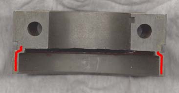
HS30-H is on the correct path. I would be very surprised to find this engine had been able to run for 100,000 plus miles with with bearing clearance of .014. Even a competition/high volume oil pump would not be able to supply enough pressure/volume, and indicated oil pressure would have been VERY low. To find out whats up, torque all the main caps in place, and measure the inside dimensions of the bearing bores. Stock specs are: 2.3866/2.3873 Then do the same thing with the bearings in place. Measure the crank main journal O.D. and then subtract that measurement from the Bearing I.D., and that will be the actual bearing clearance. Phred
-
Miles, I have a couple of new in the box #70476 lights that I bought a couple of years ago. I wounder if the 477 is just an updated 476? The 476 box also says it has a 60/55 rather than a 65/55 bulb. Could that be the difference between them? Just a thought. Phred
-
Jayru, Invest in a book by Frank Honsowetz. Titled "How To Modify Your Nissan & Datsun OHC Engine" ISBN 1-55561-237-7. It will answer most of your questions. I have built all sizes of Datsun engines over the past 30 years. Mostly for racing, but some for street. Powerful & reliable generally don't go together well. There's always compromise. For the street, you need 9.5 or 10.0:1 compression max. With triple carbs, a small cam, a little head work and a header you might see 180 hp out of a 2400. A similar 2800 might make 200/220 hp. The most radical street motor I ever built made about 260 hp. It had a stroker crank and had a disp. of 3 liters. Consider that a full race SCCA GT2 2800 (+.040) will average around 300 hp, and you will see that building a carb'ed street eng. with the same hp is not reasonable. Unless its Turbo'ed. Thats a whole 'nother ball o' worms. And a another wheelbarrow full of cash. Good luck, and go with what you think is best. Most everybody here has been around the hp block before, and they will tell you like it is. Nobody has an axe to grind, and there's a lot to be gleened from this site. Even for a semi-old guy like me. Phred
-
Carl, There are 6 diagonal oil passages in the crankshaft that transfer oil from the main journals to the rod journals. So each rod bearing is fed by a single main bearing. These 6mm I.D. diagonal holes exit near the rod journal and are plugged at the factory, and after time, grit and sludge gets packed in behind the plugs by the centrifugal force of the rotating crank. The L6 crank works great for the street as all the journals are cross drilled (except for the rear main). To race prep a Factory L6 crank oil system, the rear main journal is cross drilled, and an additional 6 diagonal holes are drilled through the crank to connect each rod journal with a second main journal. That way each rod journal is fed by two main bearings, and allows the bearings to survive extended high rpm use. Fun huh? Phred
-
Matria, There's a lot of "ifs" involved to determin if you need to remove the crank galley plugs. If you had the crank hot tanked, as opposed to just solvent cleaned, it is good insurance to remove, tap, clean, etc. The reason for this is two fold. The small plugs are aluminum, and if the bath was particularly acidic, they can erode and leave ugly stuff inside. Combine this with a little leftover sludge that was softened up by the acid bath, and its not something I want getting on my new engine bearings. The next " if " - the crank was ground, grinding sludge can hide in the galleys and come back to haunt those new bearings. On the "not necessary" side- If your engine was relatively clean inside with no damage, and the crank was just polished and solvent cleaned, you will be safe returning it to service without changing out the plugs. The galley's are drilled to 6mm dia. at the factory. Some shops will press in replacement plugs, (not preferred) or drill out the hole to accept 1/8 NPT plugs because they don't have the proper size tap. ( too much work, and can screw up the balance.) The correct repair for the Datsun crank is to buy a couple of 1/16 NPT taps, ( the crank is fairly hard and its easy to bugger a tap) and some extra 1/16 pipe plugs, ( so you can test them in the crank while tapping to set the proper depth of thread, the plug should be flush when tight.) Then install new plugs when cleaned for final assembly. For race engines that will be rebuilt frequently, I use blue Loc-tite on the plugs. But for a street engine thats hopefully going to be going for thousands of miles, you might want to use red Loc-tite. Phred
-
Brian, Your local shop should have numbered the cam towers before disassembly. I really get frustrated with the brain cell challenged people out there calling themselves engine machinists. All cam towers should have the same number and thickness of shims under each tower. They are usually .015 thick, and commonly use two under each tower. If they were not numbered, you can figure out where they go by process of elimination. Obviously, #1 has the holes for the locating plate.The rear tower has a "R" cast on the front lower side of the tower. The other three are the same casting with provision for the spray bar. If these were not numbered, the only thing you can do is play musical chairs with their location. Bolt down and torque #1 and #5 and one of the center towers to 12 lbs. with the cam in place and oil on the bearing surfaces. tighten evenly while checking the cam for ease of rotation. If the cam won't turn when tight, remove and relocate the tower to the next position and check again. do this with the center three towers till the cam turns freely when all towers are installed and torqued. Then the rockers (which were hopefully numbered) can be installed. Good luck, and always ask your machinist if they have experiance with the engine in question. Then if they screw it up, they will have to fix it properly with no extra charge to you. Phred
-
To know if you have a turbo pump you must measure the height of the rotors. Externally they are the same, and as there are aftermarket as well as original pumps, the casting # will vary. So get those new digital calipers out and measure the height and you will find one of the following: Stock Oil Pump - 1.375 Turbo Pump - 1.570 The extra power it takes to turn the larger pump is not worth considering. Both pumps use the same end housing, and pressure is adjusted with alternate springs, or by shimming the stock spring. If a new pump is installed on an old engine, and it still has low oil pressure, the culprit will be the main bearings. They act as the main restrictor to pressure. Worn out bearings with too much clearance, lets more oil pass through and the stock pump just can't keep up. That is why racing engines that usually have increased clearances, will run a high volume pump with higher pressure capability. Phred
-
Before you drop the tank, temporarily (tape) install a fuel press. gauge right up on the dash where you can see it when you're making a run. could save you a lot of work. Phred
-
Thanks for the clairification Gary. FWIW, my 71' has a build date of 7/71. HLS30-37700 Phred
-
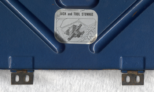
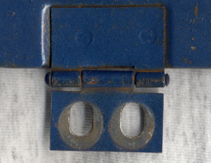
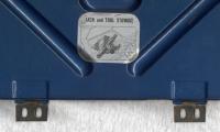
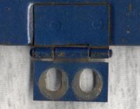
These are originals, off of a 71'. What years did they make plastic lids, or hinges? BTW, anyone can use these pics for anything they want. Heck, you can even claim you took them. Plain enough? Phred
-
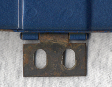
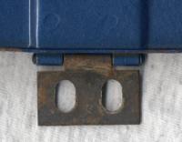
Here's my last three. Phred


-
I also agree with GaryZ240 Phred
-
Reconsider the large overbore on a 75' block. The bores will not be stable, and I have seen a few blocks with core shift, that became unusable after a .120 bore job. If you really can't control yourself, and you must bore, get an F-54 casting, and a diesel crank. Then at least it should hold together. Also keep in mind, the longer the stroke, the more torque you get, so high revs are not as important to make HP. Thats the neat thing about stroker/big bore motors, they make great HP without the high revs. Phred
-
In the forums, under: engines-Cam choice, there is a thread that will answer your questions. Phred
-
Rick, As you can see in the figures for Ed, a small change can make a big difference in compression. There are so many variables with you head, a guess here could be downright dangerous. .050 off you head? How much before? sunk valves? new Valves? You can't guess here, as a wrong guess could mean a blown engine. Phred
-
Hi Ed, You're only missing one critical measurement which I will make an educated guess on. If it varies much from my assumtion, I can easily refigure it into the formula. First, figure the known actual figures: Bore/Stroke: 3.39 X 3.11 = 2759.95 cc's Head Gasket: 3.49 X .047 = 7.37 cc's Head Gasket Shim: 3.49 X .020 = 3.14 cc's Combustion Chamber volume, (Ave.) 38.8 cc's Now, the unknown guess: Deck height: -.010 (area above the piston @ TDC) =1.48 cc's Next we just add them up to find total compressed volume: 7.37 + 3.14 + 38.8 + 1.48 = 50.79 cc's Now divide the displacement of one cly. by compressed volume, Then add 1 (a math thing to arrive at a ratio) and you have 9.06:1 compression If you delete the shim vol. of 3.14 cc's you come up with a total vol. of 47.65 and a compression of 10.65:1 Class is over for today, remember to play nice with the other Z kids. Professor Phred
-
If you can take your head to a race engine shop and get it CC'd, I can tell you what your Compression will be. I will also need to know if you are using a stock head gasket, and what the deck height is, and if those are flat top pistons. Phred
-
Imagine, if you will....... An engine with a measured, cc'd, computed compression ratio of 10.5:1. This engine has a stock cam with the intake valve closeing at about 32 degrees ABDC. Now you decide to put in a bigger cam without changing any other engine components. This cam has a longer duration and the intake valve closes at 48 degrees ABDC. Now your cranking pressure is less than before, but you still have 10.5:1 compression ratio. So the answer has to be "no". Cranking Pressure (PSI) can not be used to determin compression ratio. Phred
-
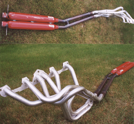
This is how I did it. The header is made by Stahl. It was made with 1.5 in. primarys, and a two inch collector/ tail pipe size. This was sized for a 240, but I'm going to run it on a 3.0 L-motor for vintage, track fun, and street mayhem. As Gary mentioned, a crossover/conector pipe can be seen installed in front of the muffs. The muffs exit at the diff. I have 3 inch ID short race muffs acting as resonators which exit at the stock location. The two pipes are only connected at the crossover point. Great sound. All bends were cut fron mandrel tubes and heli-arc welded. The muffs lay up close under the drive shaft, and the car can sit low with no road rash. Phred

-
Yes this can be done by a good machinist. However, he will need the EXACT dimension of the back of the crank, Meaning to the last thousanth of a inch. This is important as the flywheel must be a perfect fit over the crank flange to assure that the flywheel has no runout that would cause an imbalance. Phred
-
By any chance did you degree the cam? Your combination of large carbs bigger cam and low compression is a recipe for no bottom end performance. If you have a stock cam sprocket, and installed on #1 hole, you can advance the cam 4 degrees by changing to the #2 hole. Advancing the cam will help pick up the bottom end performance. Conversely, retarding the cam will loose bottom end while picking up the upper end performance. Generally, race cams don't have bottom end power, so its common to advance them a few degrees from straight up. Stock cams have good bottom end, but usually very little top end. For example, formula fords have to run a stock cam. In order to get top end power, formula ford engines are commonly retarded 4 to 5 degrees. Sometimes more. Phred
-
Ok class, look closely at the figures Deus posted. All opening and closing events are BTDC. This is imposible. The numbers sound right. So this is the likely corrected cam specs. Intake: opens @ 26 degrees BTDC (before top dead center) closes @ 66 " ABDC (after bottom dead center) add 180 " total 272 degrees duration Exhaust: opens @ 66 degrees BBDC (before bottom dead center) closes @ 26 " ATDC (after top dead center) add 180 " total 272 degrees duration Now to make these figures relavent, we need to know the lash setting, and the point at which the figures were taken. (Usually from .001 to .050 valve or lifter rise) Otherwise you cannot directly compare one cam to another. As each cam may have had readings taken at different points. As far as your lift figure of .318, This is hopefully actual cam lift. If you figure the rocker ratio of 1.5 (this number will vary, depending on rocker contact point) you come up with .477 valve lift. (you will have to subtract valve lash from this number, so it should be closer to .467 actual valve lift). There will be a pop quiz tomorrow, so I hope you took notes. Phred