


aarc240
Free Member
-
Joined
-
Last visited
Everything posted by aarc240
-
 Nothing unusual about cutting away a lot of the tower and then reinforcing the remainder with steel sheet. Of course, that's part of what strut bars are about - reinforcing something that was never designed to cope with the loads now placed on it. Porsche - not my favourite. The system I use is not real easy to describe but I'll try a word picture. Referring to the lower front suspension arm 1 the original inner pivot point hole in the crossmember is moved out 3/4" toward the outside of the car (initial or minimum negative camber setting) 2 then slotted toward the outside of the car, in my case to allow 7/16" travel for the pivot bolt 3 a shallow U channel reinforcement plate is fabricated in 3/16" steel with sides 1/4" high so that the walls of the U are the same distance apart as the outside diameter of the 'cam' plates 4 the channel is then slotted ACROSS the channel (ie towards each wall, NOT towards the open ends) to match the slotted crossmember 5 the channels (two per side) are welded to the front and rear faces of the crossmember with the walled sides vertical, ie at right angles to the ground and with the slots positioned to match the crossmember slots The cam plates are 1.25" outside diameter with the centre bolt hole being offset 0.219" and double-D configuration but the front cam plate has a double-D 0.063" larger than that in the rear plate. Both are 0.187" thick hardened steel. The inner pivot bolt has a 0.563" nominal double-D shoulder under the head with a depth of 0.157", a nominal body diameter of 0.5", a 0.5" nominal double-D shoulder with a depth of 0.157" and 0.4375"UNF threaded end. The length of pivot bolt main body is set to place the smaller double-D almost full depth into its matching cam plate when tightened fully against the centre crush tube. This does require a custom inner bush but that is easy to machine out of polyurethane stock as is the custom sized crush tube. I haven't got a spare set at the moment but when I make another or have the front end apart I'll get some pics. btw, I don't think our government knows best but I DO know that it is a lot smarter to work the system than defy it. A method 'like' a production car setup makes for a happy bureaucrat who is then much easier to deal with! In most of Australia a modified car MUST be inspected and approved before use on the roads and not doing so leaves the owner/driver totally uninsured. oops, forgot to say that the cam plates rotate INSIDE the channel. There is no lateral movement of the outside edges of the cams, the pivot bolts slide in the slots and the outer edge of the cam moves vertically in the channel. For the adjustment to change, either the bolts have come loose allowing the cams to rotate or enough force has been delivered to the pivot to either shear off one or both walls of BOTH channels or bend the pivot bolts. Either way, the lower arm will look like a pretzel first.
 -
Racing on tarmac closed circuits doesn't deliver anything like the shock loads dirt forest tracks and poor condition sealed roads do. Ever destroyed both the tyre and a Minilite alloy wheel on impact? That doesn't mean the plates won't work, just add decent outside diameter thick hardened steel washers under the adjustment bolts (or nuts) to increase the clamping surface area. If the plates are supplied with 'Unbrako' brand or similar super hard socket head bolts throw them in the bin and substitute Grade 8 or better rolled thread bolts (Unbrako tyoe fasteners are banned in areas of impact by most racing sanctioning bodies for very good reason). That style of cam adjuster is only vaguely related to the configuration I use (and used in the Valiant including '60 to '66 US models). Experience tells me that I'll bend a strut before shifting the adjustment setup I use and just as importantly, it is acceptable to ALL registration authorities in Australia as well as the peak sanctioning body (CAMS)
-
khughes, if I was going to be able to cover that subject even reasonably, I would be doimg like several others - writing a book!! Start off with amazon.com for texts on suspension and steering including at least one that covers the basic theory (like Colin Chapman's excellent work) to get a handle on it. Sit down and write out an honest assessment of what you expect out of the car (handling, ride, acceptable maintenance level etc). Even better, do that three or four times - you will end up with something close to what you need rather than want. Match up what does and doesn't agree between the car and your 'dream' sheet. A good suspension shop or, even better, a firm specialsing in building rally/race cars can then guide you from there. Don't expect to get it right the first time or perfect in the end, it's all a compromise.
-
Later 240k's have the two lights, but they are for parking brake and service brakes. PARK and BRAKE legends.
-
Kent, Are these wheels supposed to be just painted in a 'magnesium' colour (which they are not) or are they actually a magnesium alloy? If they are really an alloy of high magnesium content, how are you planning on protecting the polished rim from corrosion? I trust you realise that magnesium corrodes very, very quickly in the presence of salts, acids etc and does so RIGHT THROUGH the body of the material, not just on the surface. Geniune magnesium wheels, and any other components with a very high magnesium content, are totally coated with paint for very good reason.
-
I know, off topic but an SR20DET in a 350z ??? I hope they put that sucker on a real serious diet too (the 350Z that is!)
-
With a little luck you can get away with the 0-90 ohm sender version. I haven't yet checked the full range but a stock 240K system gives 1/2 full on the guage with 33 ohms between sender wire (yellow) and ground. Using a 36 ohm gives a very slightly higher reading and I would be VERY surprised if the guage system is anything like linear. Should have a tank out of a K soon so I'll check then and post it.
-
I forgot to include Do a cut'n'paste job on a virtual panel to create your dream design including everything (guages, lights, the lot). Colour print the final image, on more than one sheet if needed. See what it looks like in the car. Attach copies of the data on all components used together with images of the stock bare Datsun panel. Talk to your inspection / engineering people about it first (they like to feel they are being consulted).
-
Kent, You might have to rethink your guage choice - according to both Auto Meter and Rocket Industries (OZ distributor) the speedo is MPH and all others are imperial. That could be wrong, but the latest data on both websites supports it. Most speedos available aftermarket are electrical or electronic now so just get a suitable sender with it. Even better if it is electronic, it will be programmable to match the car. Worst case scenario of non-programmable speedo head and output from sender giving wrong readings can be easily fixed with a small kit from Jaycar. Check which ADR's your car has specified on the plate then do some research on those. Your car may happen to be required to meet the 'field of vision' rules and I would be very surprised if guages down over the radio would comply - a problem if you get an anal retentive type either inspecting it or later in a policeman. As you intend fitting other warning lights I would suggest sorting out the lights first and use an early panel. That way you can match all the lights in appearance and put them where you want. Have a look at http://www.altronics.com.au/ http://www.arrow.com/ http://www.dse.com.au/cgi-bin/dse.storefront http://au.farnell.com/jsp/home/homepage.jsp http://www.futureelectronics.com/ http://www.jameco.com/webapp/wcs/stores/servlet/StoreCatalogDisplay?storeId=10001&catalogId=10001&langId=-1 http://www1.jaycar.com.au/ http://www.mouser.com/ http://www.rockby.com.au/Myindex.cfm http://www.rsaustralia.com/cgi-bin/bv/rswww/home.do?cacheID=auie&returningUser=N go for optoelectronics and you will get all sorts of ideas! Art C
-
Which panel of the two variants do you need? The later one has the brake system and parking brake warning lights in small rectangilar cutouts in the lower right corner but the earlier one doesn't have them. It has a single warning light for brakes in the tacho. If you can fit the guages in behind the panel so that they are visible through the stock openings AND the guages have plastic lenses AND the guages have plastic cases AND the guages are metric then you have no problems. If all those conditions are true then the conversion even complies with our ADR's. Otherwise, if the guages are metric and you show the stock panel is metal faced then you have a good probability of it going through.
-
Not sure where you'll get a non-EGR manifold in OZ - we didn't get EFI until after July 1976 when EGR became a mandated requirement under the ADRs. Apparently these non-EGR manifolds appeared on '75 280Z US models. Not a problem, just cut the EGR extension off the manifold and have a plug TIG or MIG welded in. A quick buff over with an 80 grit disk smooths it out and if you are fussy, a 320 grit disk will get it neat. There's no reason you couldn't have the EGR valve there and mounted with a stainless steel plate under it - be pretty hard to get EGR working then! btw, the NAPS manifolds I have looked at have nearly all been L20E import or L24E (R30?) units and the injectors are NOT adequate for an L28.
-
For anyone keen enough: http://cgi.ebay.com.au/ws/eBayISAPI.dll?ViewItem&item=4646772918&ssPageName=ADME:B:SS:AU:1 BUT there are no injectors, fuel pressure regulator and a few other bits you will need. btw, injectors on a 280zx (OZ release) and an RB30 (VL Commodore or R31 Skyline) are the same parts!
-
The plenum might be bigger but the flow bench shows uneven airflow distribution to the cylinders when fitted with a single plate throttle body. I've got one of those things too and it is a pollution 'fix' not a performance device. Like NZedder I'm going with a modern ECU. I think his plan is a MegaSquirt, mine is a MicroSquirt (very little difference, conventional components vs SMD). Don't know what ignition NZedder plans, mine will be crank triggered Ford EDIS. Single plate throttle body is so that a Throttle Position Sensor will give sane output throughout the movement range, nothing to do with performance. I've now junked the NAPS and switched to a 'normal' 280zx single plate throttle body injection rig.
-
Pretty close to 7.6:1
-
Have you thought of just adding a blower (supercharger) to an L6? Inlet manifold doesn't even have to be anything special, a modified stock 240k works fine on the street. You can even use a stock exhaust manifold without losing too much (just use a big bore system, 2.5" or bigger). A bonus is if you pop a motor through too much boost or having too much fun you can just drop in another almost stock motor. There is nothing downstream of the motor to get written off by the debris unlike the exhaust side of a turbo. Smaller blowers are easy to get and cheap. If it doesn't produce enough for you, change the drive pulleys to spin the blower faster. Apparently the blower from the Toyota 2 litre engine is good for around 8000 RPM (rotor speed) without alteration. That's about 25% overdrive and I'm pretty sure not too many 2 to 3 litre engines are going to stand the resulting boost for very long, regardless of manufacturer.
-
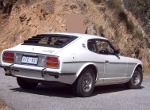
Couple of questions for the experts. 1. did the GTX come with 240Z style manifold and Hitachi carbs? 2. is the mesh in the grille the same material as the 240K, just one piece? Seems both the above would be yes based on the pics of this car.
-
You really don't need a 1" master cylinder. The difference is a little less pedal travel and a harder pedal which is easier to 'modulate' when driving on the limit. If you want a more 'normal' feel, the 15/16" will work well provided you don't switch to twin piston rear calipers. Then it will again have a longer and softer pedal. btw, a Nissan Patrol around '81 has a 1" master cylinder that is almost identical in appearance to the stock unit. It's not the caliper only you have to consider. For a front disk close to 270mm the 258 rear disks will be adequate. If you fit something around 290mm with four spot calipers and the 258mm rear disks with single piston floating calipers then you are going to have a car that locks front wheels at the slightest hint of a damp road. Try to keep the diameter of the front and rear disks reasonably close, then you will have less pain getting the balance right. Very likely if your present disks are 250mm. Anytime you go to four piston calipers you are going to need a bigger master. Use 15/16" for single piston or drum rears, 1" for two piston rears for normal street use. Step up 1/16" on either if you intend club competition (regularity etc) The bolt spacing to mount the caliper is the same on nearly all Nissan RWD cars! It's the distance from the centre of the axle to the caliper bolts that changes. You can actually bolt 200B calipers straight on a C210 strut but you won't find a rotor to match the combination! Sorry, I was sleeping at the wheel for a while!! Anyway, I have found 270mm solid disks on the front of late '75 onward C110's but that's no guarantee that someone else hasn't been in there before with C210 struts. That's the critical bit, the struts must have had 270mm disks to be an easy swap prospect. Plan on an adjustable rear brake bias compensation valve too. It will make it lots easier to dial in the package to JUST lock the front wheels before the rears. Don't get into rear wheel lock first unless you have a LOT of experience in a discipline such as speedway or rallying. HTH
-
Got it in one (or two in this case). You're right, no need to panic. Just be aware that you could get caught with a real head scratcher if the charging system isn't spot-on or the battery starts to go on you. The first symptom is usually the engine not firing while actually cranking over but trying to or actually firing as soon as you get off the starter. That's because the module isn't firing the coil while the voltage is right down. Then when the key goes from start to ignition the engine is still actually turning over and the module gets enough voltage to work and decides to fire the coil. Bloody frustrating until you suss it out.
-
oops, didn't explain that too well, did I? Correct situation is that with the 8V coil, it has a lower resistance than the transistor module is supposed to be working with so excess current will be drawn. That's when the output transistor will quit (eventually). Put the correct 12V coil in place and the higher internal resistance solves that problem. The other issue to consider is the voltage the module is operating on when the engine is cranking. You have a resistance in series with the supply such that you have 8V or so on run. When the battery is pulled down by the starter, you will still have that 4 to 5V drop across the resistance so the actual voltage getting to the module will be more like 5 to 6V. This is because the average battery will be putting out in the order of 10V while supplying the 200 to 250 amps needed to crank over the engine. Don't know what the designed minimum limit is for the module to function but the two that I tested both quit at slightly under 5V. That, in my estimation, is much too close for comfort (and is one of the reasons I don't use the 280zx system). You can probably guess that the situation becomes worse if you have increased compression, more than usual initial ignition advance and/or a lean mixture. btw, if you are down to 10kV at the plugs then you better have a rich mixture or it ain't gonna fire too happily. Art
-
I should have been a little clearer there! The relay method will certainly get you the 12V you need BUT the tacho represents a problem. The best fix is also a fairly major bit of surgery on your wiring harness AND requires a modified tacho. Getting down to basics, the harness used in the long wheelbase and short wheelbase cars is basically identical except that there is a link in the SWB harness that bypasses the tacho wiring. The tacho wiring is actually still there, just that there is no tacho anyway. This link is made inside the harness down on the right frame rail, just behind the engine mount. So the factory kindly provided a lot of what we need for a change! In our case, since we want the tacho, we have to approach this differently. The ultimate solution is to 1. open up the front harness from about the area of the starter motor wiring exit all the way to the coil wiring exit. 2. locate the (fused) ignition feed that goes back to the tacho. 3. splice into that with a black/white wire of at least 18G long enough to reach right around the front of the car to feed the ignition. This is your new 12V fused ignition feed for the coil and module. 4. neatly re-wrap the front harness 5. pull out the instrument panel and identify the tacho type. An early 240K should have a small two wire connector with the wire actually being continuous which makes a single turn through a block on the back of the tacho. 6. on the small two wire connector going to the tacho, cut the wire which has 12V ignition on it. This has isolated the tacho from the fused ignition feed. 7. have the tacho converted to an electronic sensing inner board with the single turn block eliminated. The actual meter movement and the dial face do not need to be replaced. 8. connect the sense wire now coming out the back of the tacho to the wire that goes all the way to the coil area (the old feed for the coil, no longer connected to the coil +ve) I know it sounds complicated but by working through it step by step, it's not that hard. When finished, the wire that originally went to the coil positive (and which contains that elusive ballast resistance) is used as a tacho signal wire only. The new wire from (3) above is now your ignition wire. Why go to all that trouble? Once done you have a system that looks stock standard and can be interfaced to ANY ignition setup down the front without further modification. Does it work? That's how both our '73 240K and '72 240Z are done, which run two completely different electronic ignition systems. Of course, the Z doesn't have the ballast resistance inside the harness and is more messy to source the fused ignition feed but is otherwise similar. I just hope I haven't made that sound too hairy!! hth, Art
-
If I can add a bit of info. First we should look at the old points system (Kettering igbition) In more modern example, the coil usually runs at about 8V, and in the case of the 240K the 'ballast resistor' is actually a resistance wire built into the wiring harness. No wonder it couldn't be found! On start this resistance is bypassed to provide the coil with full battery voltage which in most cases will be no more than 8 or 9V while the starter is cranking the engine. So, the result is that the coil can provide full output in both conditions. On the 280zx there is no ballast resistor and it appears that the coil is being fired from a full 12V. In that case you have three problems with the installations outlined in these posts. 1. the ignition module is being supplied with reduced voltage via the built in ballast resistor 2. eventually the output transustor is going to cry 'enough!' since it is supplying a reduced voltage to the coil with a specific resistance which will result in increased current (remember E=IR or I=E/R) 3. if you fix the coil resistance issue with a 12V unit, you will increase the resistance thus saving the module but the output (ie spark) will be weaker because less current is flowing in the coil primary. The fix is bypass the resistance wire, install a 12V coil and connect that 'condenser' (actually a capacitor) from coil positive to ground. That's the 'little cylinder', and it is VERY important in that it also protects the module from electrical spikes. The other 'condensers scattered around the system will help noise induced through the radio power supply but they are much to far away for the safety of the module. hth Art
-
"There was at least 1 KPGC10 sold to an RAF pilot then stationed over here and was frequently seen in Woomera SA. afaik, he shipped that car to Germany when he was posted there."
-
No, it is anecdotal evidence. If it provides a clue for anyone well and good. Yes, and proof usually can best be obtained by constructive cooperation. That is something I see very differently. Trained originally as a tradesman (Toolmaker) I know very well how and why engineering drawings are done. I also know they are costly to produce, particularly back at a time when each drawing had to be produced individually and by hand. Somehow we see here a company that will waste money on irrelevant drawings yet would be so unlikely to lay out a small sum to localise a product as with a speedometer. Yair, right! Never mind, there's one in every bunch. Art
-
Maybe they did fit some. That would be terribly inconvenient, wouldn't it?
-
I take it then that you were in and out of Datsun dealers in 1970? My first Datsun was purchased new in late February 1970, first sight of the 240Z was five weeks later in the workshop being predelivered. The first L4 'DATSUN 1600 OHC' cover I saw was on the new engine I was buying (along with a lot of other bits) to stuff into the Datsun 1200 coupe I had bought less than two months before. That was at the same time the 240Z was seen. Even though that 1600 powered Datsun coupe was in and out of the dealer floor for display on a regular basis, the first time I saw a Nissan cover on either an L4 or an L6 was quite some time later.